Thus far, we have examined how the transmittance through a Fabry-Perot instrument varies with surface separation d and angle θ1. However, the main purpose of a Fabry-Perot instrument is to measure small changes in the wavelength of light, which similarly affect the value of Φ Consider a Fabry-Perot interferometer where the transmittance through the instrument is plotted as a function of plate spacing d.
At certain spacings, Φ happens to be a multiple of 2π for the wavelength λvac. Next, suppose we adjust the wavelength to λvac + ∆λ while observing the locations of these fringes. As the wavelength changes, the locations at which Φ is a multiple of 2π change. Consequently, the fringes shift as seen
shift throughout a whole period, and the picture looks the same. This brings up an important limitation of the instrument. If the fringes shift by too much, we might become confused as to what exactly has changed, owing to the periodic nature of the fringes.
If two wavelengths aren’t sufficiently close, the fringes of one wavelength may be shifted past several fringes of the other wavelength, and we will not be able to tell by how much they differ. This introduces the concept of free spectral range, which is the wavelength change ∆λFSR that causes the fringes to shift through one period. We find this by setting (4.30) equal to 2π. After rearranging.
We next consider the smallest change in wavelength that can be noticed, or resolved with a Fabry-Perot instrument. For example, if two very near-by wavelengths are sent through the instrument simultaneously, we can distinguish them only if the separation between their corresponding fringe peaks is at least as large as the width of an individual peak.
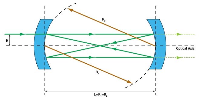
This situation of two barely resolvable fringe peaks is illustrated in a diverging beam traversing an etalon. We will look for the wavelength change that causes a peak to shift by its own width. We define the width of a peak by its full width at half maximum (FWHM). Again, let Φ be a multiple of 2π where a peak in transmittance occurs. In this case, we have from (4.23) that.
Multilayer Coatings
As we saw in Example 4.2, a single coating cannot always accomplish the desired effect, especially if the goal is to make a highly reflective mirror. For example, if we want to make a mirror surface using a dielectric (i.e. nonmetallic) coating, a single layer is insufficient to reflect the majority of the light. In P4.5 we find that a single dielectric layer deposited on glass can reflect at most about 46% of the light, even when we used material with very high index. We would like to do much better, and this can be accomplished with multilayer dielectric coatings. Multilayer dielectric coatings can perform considerably better than metal surfaces such as silver and have the advantage of being less prone to damage.
Periodic Multilayer Stacks
Many different types of multilayer coatings are possible. For example, a Brewster’sangle polarizer has a coating designed to transmit with high-efficiency p-polarized light while simultaneously reflecting s-polarized light with high efficiency. The backside of the substrate is left uncoated where p-polarized light passes with 100% efficiency at Brewster’s angle.
Last word
This formula relies on the condition AD −BC = 1, which is true for matrices of the form (4.55) and (4.63) or any product of them. Here, A, B, C, and D represent the elements of a matrix composed of a block of matrices corresponding to a repeated pattern within the stack.
The tattoo culture has experienced a significant rise in popularity over the years, becoming more mainstream and widely accepted. Tattoos have a long and rich history, serving as a form of self-expression and a symbol of cultural significance. From ancient civilizations to modern times, tattoos have held various meanings and purposes.