Multiple Parallel Interfaces
we studied the transmission and reflection of light at a single interface between two (isotropic homogeneous) materials with indices ni and not. We found that the percent of light reflected versus transmitted depends on the incident angle and on whether the light is s- or p-polarized. The Fresnel coefficients, connect the reflected and transmitted fields to the incident field. Similarly, either Rs and Ts or Rp and Tp determine the fraction of incident power that either reflects or transmits.
we consider the overall transmission and reflection through multiple parallel interfaces. We start with a two-interface system, where a layer of material is inserted between the initial and final materials. This situation occurs frequently in optics. For example, lenses are often coated with a thin layer of material in an effort to reduce reflections. Metal mirrors usually have a thin oxide layer or a protective coating between the metal and the air.
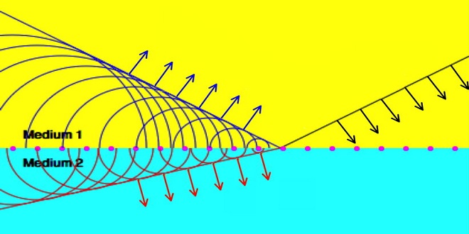
We can develop reflection and transmission coefficients r tot and t tot, which apply to the overall double-boundary system, similar to the Fresnel coefficients for a single boundary. Likewise, we can compute an overall reflectance and transmittance R tot and T tot. These can be used to compute the ‘tunneling’ of evanescent waves across a gap between two parallel surfaces when the critical angle for total internal reflection is exceeded.
Double-Interface Problem Solved Using Fresnel Coefficients
Consider a slab of material sandwiched between two other materials as depicted in Fig. 4.1. Because there are multiple reflections inside the middle layer, we have dropped the subscripts i, r, and t used in chapter 3 and instead use the symbols.
As of yet, we do not know the amplitudes or phases of the net forward and net backward traveling plane waves in the middle layer. We denote them by E (s) 1 and E (s).
Before we continue, we need to specify an origin so that we can calculate phase shifts associated with propagation in the middle region. Propagation was not an issue in the single-boundary problem studied back in However, in the double-boundary problem, the thickness of the middle region dictates phase variations that strongly influence the result. We take the origin to be located on the first interface, as shown in Since all fields in and are evaluated at the origin (y, z) = (0, 0), there were no phase factors needed.
We will connect the plane-wave fields across the second interface at the point r = zˆd. The appropriate phase-adjusted2 field at (y, z) = (0,d) is E (s) 1e ik1·r = E (s) 1e i k1d cosθ1 , since E (s) 1 is the field at the origin (y, z) = (0,0). The transmitted field in the final medium arises only from the forward-traveling field in the middle region, and at our selected point.
The initial reflection from the first interface is described by the first term r 01s. The numerator can be simplified algebraically, but we have left it in this longer form to emphasize the physics of the situation. The numerator of the second term describes the effect of light that transmits through the first interface, propagates through the middle layer, reflects from the second interface, propagates back through the middle layer, and transmits back through the first interface to interfere with the initial reflection. The denominator of the second term accounts for the effects of multiple-reflection feedback.
Transmittance through Double-Interface at Sub-Critical Angles
We are now in a position to calculate the fraction of power that transmits through or reflects from a double-interface arrangement. Because the transmission coefficient has a simpler form than the reflection coefficient, it is easier to calculate the total transmittance T tot s and obtain the reflectance, if desired, from the relationship)
Transmittance through Double-Interface at Sub-Critical Angles
The quantity T max s is the maximum possible transmittance of power through the two surfaces. The single-interface transmittances and reflectances are calculated from the single-interface Fresnel coefficients in the usual way as described. The numerator of T max s represents the combined transmittances for the two interfaces without considering feedback due to multiple reflections. The denominator enhances this value to account for reinforcing feedback in the middle layer.
Last word
The exact argument of the sine function, Φs, can strongly influence the transmission. The term 2k1d cosθ1 represents the phase delay acquired during roundtrip propagation in the middle region. The terms ϕr 10 s and ϕr 12 s account for possible phase shifts upon reflection from each interface. They are defined indirectly by writing the single-boundary Fresnel reflection coefficients in polar format.