Advanced engine management technology
Speed density and fuel calculations
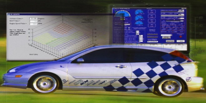
Engine management systems that do not use an airflow sensor rely on the speed–density method for determining the required fuel quantity. Accurate measurement of the manifold absolute pressure (MAP) and intake air temperature is essential with this technique.
Ignition timing calculation
Data relating to the ideal ignition timing for a particular engine are collected from dynamometer tests and operational tests in the vehicle. These data are stored in the form of look-up tables in ROM. These look-up tables hold data relative to the speed and load of the engine. The number of look-up values is determined by the computing power of the microcontroller, in other words, the number of bits,
Inputs from speed and load sensors are converted to digital numbers and these form the reference to find the ideal timing value. A value can also be looked up for temperature correction. These two digital numbers are now added to give a final figure. Further corrections can be added in this way for conditions such as overrun and even barometric pressure if required.
This ‘timing number’ is used to set the point at which the coil is switched off; that is, the actual ignition point. The ECU receives a timing pulse from the ‘missing flywheel tooth’ and starts a ‘down counter’. The coil is fired (switched off) when the counter reaches the ‘timing number’. The computing of the actual ‘timing number’ is represented by Figure 10.60.
To prevent engine damage caused by detonation or combustion knock, but still allow the timing to be set as far advanced as possible, a knock sensor is used. The knock sensor (accelerometer) detects the onset of combustion knock, but the detection process only takes place in a ‘knock window’.
Dwell calculation
The ‘dwell number’ is used in a similar way to the ‘timing number’ in the previous section except that this time, the ‘dwell number’ is used to determine the switch-on point of the coil during the operation of the down counter.
Injection duration calculation
The main criteria for the quantity of fuel required for injection are engine speed and load. Further corrections are then added. represents the process carried out in a digital electronic control unit to calculate injection duration.
Operation and maintenance is the stage when the program is actually in use. Occasionally slight errors do not come to light until this stage, such as a slight hesitation during acceleration at high altitude or some other obscure problem. These can be rectified by program maintenance for inclusion in later models
Simulation program
Automotive Technology (AT) is a training and diagnostic software program. It works in conjunction with this textbook and online learning. All complex electronically controlled systems can be considered as having
Developing and testing software
Here is, of course, more than one way of producing a ‘computer’ program. Most programs used in the electronic control unit of a vehicle digital control system are specialist applications and, as such, are one-off creations. The method used to create the final program is known as the ‘top-down structured programming technique’. Following on from a ‘need’ for the final product, the process can be seen to pass through six definable stages.
Are you ready to make the most out of Join Blooket? Discover some amazing tips and tricks that will boost engagement and manage classroom dynamics effectively. Let’s dive in!
Last word
Coding is the stage at which the task begins to be represented by a computer language. This is when the task becomes more difficult to follow as the language now used is to be understood by the ‘computer’.

